Home > Technical Support > Molding Technology > Molding Technology for DURACON(R) POM
Product Design / Strength of Molded Products
7. Product Design 7.5 Strength of Molded Products
Table 7-4 Possible originating points of breakage
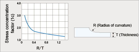
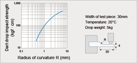
Problems related to shape (a) Sharp corners Since strain at the time of molding and stress at loading is concentrated at sharp corners, sharp corners are apt to cause breakage. For this reason, corners should be provided with as large a curvature as possible within the allowable range (Figs. 7-6 and 7-7).
(b) Weld line and gate Table 7-5 shows tensile strength measured on test pieces having a weld line where stress is applied. This table shows that elongation at break decreases to approximately 1/2 to 1/3 that of normal test pieces, while tensile strength is similar to that of a sample with no weld line. Designing should be performed and gate position should be selected so that as little stress as possible is applied on the weld line and gate section. Since incomplete adhesion of the weld line also becomes a cause of breakage, attention should be paid to molding conditions. Table 7-5 Effect of weld on tensile properties
Test piece: ISO tensile test piece (2mm thickness)
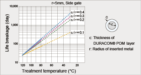
(c) Flash and moldings containing metal insert If flash occurs in an area where stress is applied, the flash may crack, and then these cracks may act as notches, which cause breakage. Wall thickness of resin in metal insert moldings should be determined in consideration of breakage from creep. When a metal insert has an edge and when flash occurs on the surface of the insert, creep life until breakage becomes so short that careful attention should be paid to the metal edge and flash.
|
||||||||||||||||||||||||||||||||||||||||||||||||||||||||||||||