Home > Technical Support > Molding Technology > Molding Technology for DURACON(R) POM
Product Design / Deformation
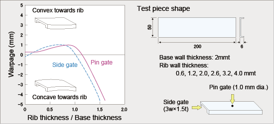
7. Product Design 7.3 Deformation (a) Warpage of plates having ribs Causes:
Table 7-2 Warpage of plates with ribs
Warpage: Minus values represent concave deformation towards ribs.
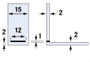
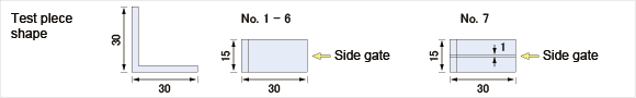
(b) Tilt deformation of L-shaped and U-shaped moldings In general, L-shaped and U-shaped moldings suffer deformation towards the center. Causes:
Countermeasures:
Table 7-3 Deformation of L-shaped moldings
The values are tilt angle. The unit is arc degree. Negative values represent outward tilting.
(c) Internal warping of box-type moldings In general, box-type moldings suffer internal warping of outer wall. The causes are the same as those with L-shaped and U-shaped moldings: shrinkage in a corner side increases as mold temperature in the core side increases. Countermeasures:
(d) Warpage of disk-shaped moldings With disk-shaped moldings, surge deformation or umbrella-shaped deformation may occur. Causes:
Countermeasures:
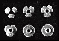
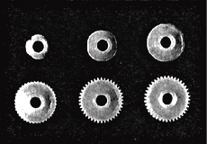
The number and position of gates should be considered for improving roundness. In general, a better result is obtained when three or more pinpoint gates are employed rather than one-point side gate and one pinpoint gate. It is appropriate to arrange the three pinpoint gates at the points of an equilateral triangle. Roundness is improved when the gate position is set in the center or near the center of a molding and resin is flowed concentrically from the center to the circumference. As shown in Fig. 7-3, good accuracy can be obtained when the resin flows concentrically.
Fig. 7-3 Gate positions of gears and their flow patterns
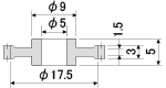
(e) Warpage of cylindrical molding Moldings of long cylindrical shapes tend to have the shape of a tsuzumi, a Japanese hand drum having outside diameters larger at both ends and smaller in the middle. This is because melted polymer solidifies sooner at the ends than in the middle, and such conditions can be improved by decreasing the wall thickness: for example, by adopting a double-wall cylindrical structure. For such a structure, when adopted, the thickness of ribs connecting the outer and inner walls should be made as thin as possible in order to reduce effects of sinking by the rib.
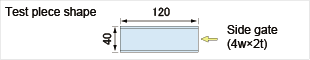
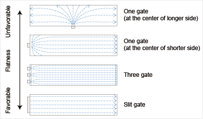
(f) Warpage of rectangular molding When a gate is arranged on the longer side of a slender molding, the molding is apt to experience concave warpage towards the gate side. For this reason it is desirable to locate the gate on the shorter side of the molding. Examples are shown in Fig. 7-4.
(g) Molding conditions and warpage Molding conditions relating to warpage include injection and holding time, cooling time, injection speed and mold temperature. Careful attention should be paid to these factors: (1) Injection and retention time The sum of injection time and retention time is set longer than the gate seal time. If the sum of these times is set shorter than the gate seal time, warpage may increase, as shown in Fig. 4-8.
(2) Cooling time As a rule, warpage decreases with an increase in cooling time.
(3) Injection speed Depending on mold shape, warpage may vary with injection speed. In some cases, higher injection speed results in less warpage, but in other cases the opposite effect occurs. Therefore, it is necessary to determine optimum conditions for minimizing warpage by conducting tests at various speeds.
(4) Mold temperature Warpage decreases with low mold temperature. However, when moldings are used at elevated temperature, warpage and dimensional change due to after-shrinkage may cause problems. The optimum mold temperature should be selected in consideration of these requirements.
|
||||||||||||||||||||||||||||||||||||||||||||||||||||||||||||||||||||||||||||||||||||||||||||||