4. Molding Conditions
4.8 Molding Cycle
4.8.1 Injection and Pressure Retention Time
The molding cycle is generally set such that the sum of injection time and retention time is slightly longer than the gate seal time. As shown in Fig. 4-5, the gate seal time is the shortest time within which material equal to the weight of the molding is injected. If the sum of injection time and retention time is shorter than the gate seal time, the following problems may occur:
- Mold shrinkage increases. (Fig. 4-6)
- Dimensional accuracy decreases. (Fig. 4-7)
- Voids and sink marks are generated.
- Deformation increases. (Fig. 4-8)
- Impact strength decreases. (Fig. 4-9)
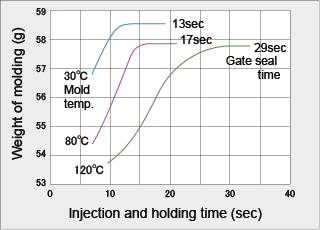
Fig. 4-5 Weight of molding and gate seal time |
Molding conditions:
Cylinder temperature: 190°C
Injection pressure: 75MPa
Injection speed: 17mm/s
Mold:
120×120×3mm flat plate
(side gate 4w×2t) |
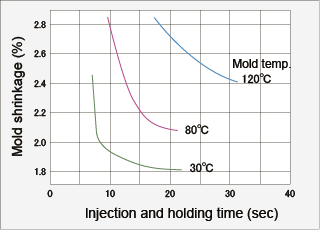
Fig. 4-6 Mold shrinkage and gate seal time |
Molding conditions:
Cylinder temperature: 190°C
Injection pressure: 75MPa
Injection speed: 17mm/s
Mold:
120×120×3mm flat plate
(side gate 4w×2t) |
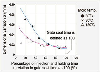
Fig. 4-7 Dimensional variation and gate seal time |
Test piece:
ASTM tensile test piece
(thickness: 3.2mm)
Measured section:
Longitudinal direction
(213mm) |
The gate seal time must be measured on actual moldings, as it varies with the relation between the capacity of the molding machine and the material weight per shot, the gate size, the molding wall thickness at gate section, and molding conditions. Refer to the data for test pieces shown in Table 4-1 and Table 4-2.
Table 4-1 Gate seal time (side gate)
| Mold temp. (°C) |
Wall thick. (mm) |
Gate size (w × t) |
Gate seal time (sec.) |
| M90-44 |
GH-25 |
| 40 |
1 |
2 x 1 |
4 |
- |
| 2 |
2 x 1 |
9 |
6 |
| 4 x 2 |
9 |
6 |
| 3 |
2 x 1 |
11 |
10 |
| 4 x 2 |
17 |
10 |
| 6 x 3 |
20 |
11 |
| 4 |
2 x 1 |
14 |
11 |
| 4 x 2 |
20 |
15 |
| 6 x 3 |
26 |
16 |
| 60 |
1 |
2 x 1 |
4 |
- |
| 2 |
2 x 1 |
10 |
6 |
| 4 x 2 |
10 |
7 |
| 3 |
2 x 1 |
14 |
10 |
| 4 x 2 |
19 |
12 |
| 6 x 3 |
21 |
12 |
| 4 |
2 x 1 |
15 |
13 |
| 4 x 2 |
22 |
17 |
| 6 x 3 |
31 |
18 |
| 80 |
1 |
2 x 1 |
5 |
3 |
| 2 |
2 x 1 |
11 |
7 |
| 4 x 2 |
12 |
7 |
| 3 |
2 x 1 |
17 |
14 |
| 4 x 2 |
22 |
14 |
| 6 x 3 |
24 |
15 |
| 4 |
2 x 1 |
18 |
16 |
| 4 x 2 |
27 |
20 |
| 6 x 3 |
34 |
21 |
GH-25: Glass fiber 25% reinforced grade, Test piece: 80×80mm flat plate
Table 4-2 Gate seal time (pin gate)
| Mold temp. (°C) |
Wall thick. (mm) |
Gate size
(Ø) |
Gate seal time (sec.) |
| M90-44 |
GH-25 |
| 40 |
1 |
0.5 |
3.4 |
2.8 |
| 1.0 |
3.4 |
2.8 |
| 2 |
1.0 |
8.6 |
6.2 |
| 1.5 |
9.0 |
6.4 |
| 3 |
1.5 |
13.8 |
10.6 |
| 2.0 |
15.8 |
11.2 |
| 60 |
1 |
0.5 |
3.8 |
2.8 |
| 1.0 |
3.8 |
2.8 |
| 2 |
1.0 |
9.8 |
7.0 |
| 1.5 |
10.6 |
7.8 |
| 3 |
1.5 |
16.6 |
12.8 |
| 2.0 |
18.2 |
12.8 |
| 80 |
1 |
0.5 |
4.2 |
3.4 |
| 1.0 |
4.2 |
3.4 |
| 2 |
1.0 |
11.8 |
7.8 |
| 1.5 |
12.6 |
9.0 |
| 3 |
1.5 |
19.2 |
15.8 |
| 2.0 |
20.6 |
16.8 |
GH-25: Glass fiber 25% reinforced grade, Test piece: 50×50mm flat plate
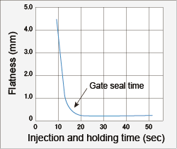
Fig. 4-8 Warpage and gate seal time
|
Test piece:
120mm diameter disk
Thickness 2mm
(1.5mm dia. pin gate) |
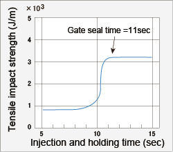
Fig. 4-9 Impact strength and gate seal time
|
Molding conditions:
Cylinder temperature: 180°C
Mold temperature: 80°C
Injection pressure: 100MPa
Injection speed: 50mm/s
Mold:
Tensile impact test piece
(2.5mm dia. pin gate) |
4.8.2 Cooling Time
Fig. 4-10 shows approximate times to knock out DURACON® POM M90-44 molded products as obtained by actual measurement and calculation. In general, holding pressure time should be a little longer than gate sealing time as mentioned before. Cooling time is determined by plasticating time plus product knockout time (holding pressure and cooling time). Moreover, a longer cooling time may be necessary when the product wall is thick, the molded products have a heat-accumulating thin and long core, or deformation is a problem.
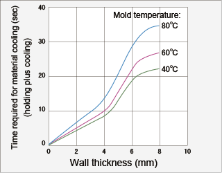
Fig. 4-10 Minimum times for knockout of moldings
|
Test piece:
80×80mm flat plate, 1-8mm thick
Side gate:
2w×1t (case of thick 1-4mm)
4w×2t (case of thick 5-8mm)
Calculation method:
The minimum time for knockout is calculated from the estimated ratio in normal moldings, which is based on the ratio of solidified layer capable of being knocked out in an 80×80mm flat plate. |
|