Home > Technical Support > Molding Technology > Molding Technology for DURACON(R) POM
Molding Conditions / Condition Setting
4.3 Cylinder Temperature 4.3.1 Example Temperature Distribution of the Cylinder The melting point of DURACON® POM is approximately 165°C, but from the practical point of view a material temperature of 190-210°C (if possible 200-210°C) is appropriate. The material temperature is generally set 10-15°C higher than the cylinder temperature (front section). An example temperature distribution of the cylinder is shown below, and it is recommended that the temperature be directly measured by a thermometer inserted into the block of molten material as it exits the nozzle. Configuration example of cylinder temperature:
When the material temperature is not appropriate, the following problems may result:
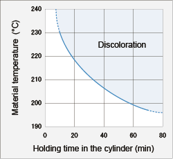
4.3.2 Discoloration by Holding The discoloration of a molding is related to the material temperature and retention time in the cylinder of the molding machine. Although the discoloration slightly varies with grades, the general discoloration limit for DURACON M90-44 is shown in Fig. 4-4 The permissible retention time is determined by discoloration rather than deterioration of properties.
Fig. 4-4 Discoloration range at elevated temperature 4.4 Mold Temperature Although the normal mold temperature of DURACON is 60-80°C, the actual mold temperature should be determined in consideration of properties of moldings, surface appearance, dimensional change in use, molding cycle time and other factors. For example, in case of moldings used in elevated temperature, mold temperature must be higher than the application temperature, or molded products must be annealed in order to prevent dimensional change during use. Moldings which require mirror surfaces are often molded at a mold temperature as high as 120°C. When the mold temperature is set at temperatures as low as 30-40°C in order to shorten the molding cycle, the following points should be taken into account:
Uniformity of mold temperature distribution should be taken into account for prevention of warpage. 4.5 Injection Pressure Although the injection pressures of DURACON are as follows, the actual pressure is determined in consideration of appearance and dimension of moldings, flowability, mold shrinkage and the required properties of the moldings. Example injection pressure setting: Injection pressure: 100MPa Holding pressure: 50-100MPa Turning point from injection process to holding process: the point at which 80-90% of the cavity is filled. When the injection pressure is not appropriate, the following problems may occur:
4.6 Injection Speed Although the normal injection speed is 5-50mm/s (0.3-3m/min), the actual speed is determined in consideration of molding shape, wall thickness, required properties of moldings, runner thickness, gate size, etc.:
When the injection speed is not appropriate, the following problems may occur:
4.7 Screw Rotational Speed and Back Pressure From the standpoint of temperature variance of molten resins, theoretically it is desirable that screw rotational speed be lower and the back pressure be higher, but the following parameters are practical from the productivity point of view: Example screw rotational speed / back pressure: Screw rotational speed: 100-150 rpm Back pressure: 0-5MPa It should be taken into consideration that excessively low back pressure causes unstable metering due to the trapping of air and excessively high back pressure causes drooling from the nozzle and prolongs the plasticization time.
|