Home > Technical Support > Molding Technology > Molding Technology for DURAFIDE(R) PPS
4. Mold Design
(1) Mold Materials
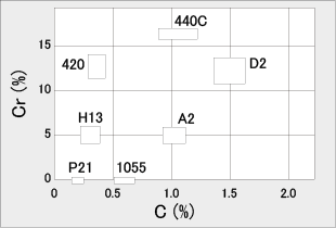
Since DURAFIDE® is filled with glass fibers and other fillers, abrasion of molds should be taken into consideration. Considering a small amount of corrosive gas to be generated when molding, a mold steel with abrasion resistance and corrosion resistance is necessary. Fig. 4-1 shows AISI standard steel material. For DURAFIDE molding, such mold steels as D2, 420 and 440C are recommended. To extend mold life, surface treatment of the mold is effective. In this regard, a ceramic coating by PVD technique using chromium nitride (CrN), for example, is recommended. (See Table 4-1.) |
|
Fig. 4-1 AISI Standard Steel Material Plot |
| Table 4-1 Ceramic Coating by PVD Method |
Coating type |
Hue |
Hardness Hv) |
Coefficient of friction |
Corrosion resistance |
Abrasion resistance |
Oxidation resistance |
TiN |
Gold |
2000 - 2400 |
0.45 |
|
|
|
ZrN |
White gold |
2000 - 2200 |
0.45 |
|
|
|
CrN |
Silver-white |
2000 - 2200 |
0.30 |
|
|
|
TiC |
Silver-white |
3200 - 3800 |
0.10 |
|
|
|
TiCN |
Gray purple |
3000 - 3500 |
0.15 |
|
|
|
TiAIN |
Dark purple |
2300 - 2500 |
0.45 |
|
|
|
Al2O3 |
Gray |
2200 - 2400 |
0.15 |
|
|
|
DLC |
Black |
3000 - 3500 |
0.10 |
|
|
|
|
(2) Mold Temperature Control
Since molds should be heated to over 130°C, cartridge heaters are normally used. More uniform mold temperature distribution is obtained if pressurized hot water temperature control or oil temperature control is used.
Heaters should also be provided in the stationary and movable clamping plates of molds. |
(3) Sprues and Runners
Sprues should be tapered by 2 to 3 degrees, and round or trapezoidal runners are standard. At the tip of sprues and runners, a cold slag well must be provided without fail. Polishing the sprue section very well is necessary. If polishing is insufficient, mold release troubles may result. |
(4) Gates
Though the pin-point gate and tunnel gate are adoptable, the side gate system affords a greater design freedom. The size of pin-point gate is 0.6mm in diameter at the minimum and mostly from 0.8 to 1.2mm in diameter. Above all, a size of 1mm in diameter or larger is desirable.
Gate location is important and attention must be paid to weld points and anisotropy caused by fibrous fillers. |
(5) Wall Thickness of Molded Products
Constant wall thickness over 0.8mm is standard rule of design. If the wall thickness is 0.2mm, for 1140A1, the longest distance of flow is 7mm. In Fig. 4-2 and Table 4-2 is show the flowability of DURAFIDE. |
|
Fig. 4-2 Flowability of DURAFIDE® 1140A1 |
|
Table 4-2 Flowability Comparison of DURAFIDE® Grades |
0220A9 |
1130A1 |
1130A64 |
1130T6 |
1140A1 |
1140A6 |
0.9 |
1.0 |
1.3 |
1.0 |
1.0 |
1.2 |
1140A64 |
1140A7 |
1150A64 |
6150T6 |
6165A4 |
6165A6 |
1.4 |
1.9 |
1.2 |
1.2 |
0.7 |
0.8 |
6165A7 |
6465A62 |
6565A6 |
6565A7 |
2130A1 |
3130A1 |
0.9 |
1.2 |
0.8 |
1.3 |
0.9 |
1.7 |
6345A4 |
7140A4 |
|
|
|
|
1.6 |
1.1 |
|
|
|
|
|
| |
With the flow length of 1140A1 as 1.0 |
| |
Mold used
Cylinder temp
Mold temp
Injection pressure |
: Bar flow (1 mmt)
: NH320-320-305-290(°C)
: 150°C (100°C for 6565A6)
: 73.5MPa |
(6) Release Taper
The standard release taper is 1 to 2 degrees. When dimensional accuracy is particularly required, a release taper of approximately 1/4 to 1/2 can be adopted. |
(7) Air Vents
A vent port of about 0.005 to 0.008mm deep, 5mm wide and 2 to 3mm long should be provided. The mold is machined for 0.5 to 1mm deep from the air vent end to release air into the atmosphere. It is more effective if air vents are also provided also at sprue and runner sections. If air vents are not adequate, poor gloss of molded products, degradation of weld strength, short shot and burns may sometimes result. |
(8) Ribs
It is more effective to increase the number rather than enlarging the height and thickness of ribs. The base area of the rib is one half of the wall thickness of product and the release taper should be greater than 2 to 3 degrees. |
|