Home > Technical Support > Molding Technology > Molding Technology for DURANEX(R) PBT
Deformation
4.2 Deformation Uneven shrinkages of various sections of a molded part are the major cause of deformation. Inversely, if a part shrinks uniformly, then no deformation occurs. Though all of the following three causes are major reasons for uneven shrinkage in a part, the anisotropy of the shrinkage between the flow and the transverse directions is the most important cause of deformations in reinforced grades of DURANEX® PBT. 1. Non-uniform section thickness 2. Non-uniform mold temperature and pressure of melt in a cavity 3. Anisotropy of shrinkage due to flow direction
(1) Shape Design vs. Deformation Because the configuration greatly affects deformation, it is essential to design a part with shapes that minimize deformation so long as it conforms to its function. The typical deformation of some popular shapes are explained below.
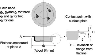
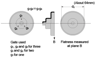
(a) Disc –shaped Parts Roundness and plane flatness of DURANEX 3300 is shown as follows:
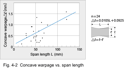
(b) Box-type Parts The relation between concave warpage and span length is shown in Fig. 4-2. There is a rather large scattering in the data, but the figure will give a rough estimation of the amount of concave warpage.
Measures to overcome concave warpage are providing the part with ribs to shorten the span length or designing molds with an inverse warpage. Proper gate design is also effective; i.e., a pin-point gate at the center functions better than a side gate as shown in Table 4-1. Core cooling is also useful; e.g. when the core is cooled, concave warpage is reduced to as little as 20 to 30% in case of DURANEX 2000 and 2002 and to about 60% in case of glass fiber reinforced grades. Table 4-1 Concave Warpage vs. Gate Design (Unit: mm)
(c) L-shaped Parts The deviation from right angle for various L-shaped sections is shown in Table 4-2. A triangular rib like that in shape #8 is found to be the most effective way to prevent deformation. Table 4-2 Deviation from Right Angle (in degrees)
Forced temperature differences between the core and the cavity mold halves at the corner are effective to reduce deviation from right angle for grades like DURANEX 2000, 2002 and 6300B, as seen in Table 4-3. In case of glass fiber reinforced grade, deviation from right angle depends on the gate position as shown in Table 4-4, which indicates some instances where gates located at the corner produce less deviation than gates located at the tip, which is the conventional position. Table 4-3 Effect of Corner Cooling on Deviation in L-shaped Parts (Unit: degrees)
Table 4-4 Gate Location vs. Deviation in L-shaped Parts (Unit: degrees)
(d) Ribbed Plates One of the measures to improve stiffness of a part is to provide it with ribs, but some ribs tend to increase deformation of the part. Examples are listed in Table 4-5. The deformations of shape #1 that has symmetrical ribs at both ends is similar to that of shape #6 that has no ribs. Plates having ribs on only one side have some warpage making the ribbed side convex. These results can be used to minimize warpage. Table 4-5 Warpage (mm) of Ribbed Plates
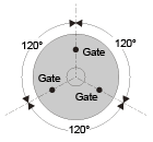
(2) Gate Design vs. Deformation [Example 1] Impeller (3300) (Unit: mm)
[Example 2] Round parts (valve) No.2, housing (3300) (Unit: mm)
[Example 3] Round parts (valve) No.1, top and bottom lids (3300) (Unit: mm) (Unit : mm)
(3) Molding Conditions vs. Deformation Molding conditions which are closely related to deformation of a part are mold temperature, cooling time and those factors which affect pressure of melt in the cavity, such as gate size, injection speed and dwell time.
(a) Mold temperature As examples, the results obtained from round parts made of DURANEX 3300 are listed in Table 4-6. There is an indication that the lower the mold temperature, the better the roundness and the flatness. Table 4-6
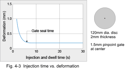
(b) Injection and dwell time The relation between injection and dwell time and flatness of a disc 120 mm in diameter and 2 mm in thickness, molded through a center pin-point gate, is shown in Fig. 4-3. This figure shows that if injection and dwell time is shorter than the gate seal time, deformation is greatly increased. This is a very important point in setting the molding cycle.
(c) Injection speed The effect of injection speed on deformation is not so great. However, deformation tends to reduce as injection speed increases. Examples are shown in Table 4-7. Table 4-7
|
||||||||||||||||||||||||||||||||||||||||||||||||||||||||||||||||||||||||||||||||||||||||||||||||||||||||||||||||||||||||||||||||||||||||||||||||||||||||||||||||||||||||||||||||||||||||||||||||||||||||||||||||||||||||||||||||||||||||||||||||||||||||||||||||||||||||||||||||||||||||||||||||||||||||||||


