Home > Technical Support > Gears
Noise Reduction Technology for Plastic Gears
-Points to note in effective noise reduction for helical gears-
| 1. Introduction |
Polyplastics is a materials manufacturer, but in addition to just materials we have been making proposals that include design technology since the time of our founding. Many people think of design technology as being outside the domain of materials manufacturers, but design technology proposals by engineering plastics experts have helped to drive product quality advancements in various fields. One of these was noise reduction technology for plastic gears which we introduced around three years ago for spur gears. As a continuation of that story, we decided to focus on points to note in effective noise reduction for helical gears. |
| Plastic gear noise reduction methods - Summarized in previous report | ||
| Frequency analysis of noise in spur gears shows that gear mesh frequency is the largest contributing factor. This can be broken down into the following three types. | ||
1) Repeated change in the number of teeth meshing |
||
|
• | Contact ratio is typically between 1 and 2, which means that part of the time two pairs of teeth are in contact, and during the remaining time one pair is in contact. Noise occurs when deformation volume changes in this situation |
| • | Changing to a gear with deep tooth (form) is effective | |
2) Reversed vector of frictional force in pitch points |
||
|
• | The cause is a reversal in the vector of frictional force in the diametrical direction when the teeth mesh |
| • | Using grease or high sliding grades to lower the coefficient of friction is effective | |
3) Compatibility of the pitch with the mating gear |
||
| • | Shrinkage during molding can cause slight misalignment of the module in resin gears. When this happens, normal pitch also ends up misaligned | |
| • | Noise occurs when combined with gears of different normal pitch | |
|
• | Adjusting to the same normal pitch by adjusting the molding conditions is effective |
| 2. Noise reduction effect in helical gears | |||||||
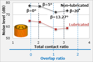
In the case of spur gears, they normally rotate while alternatingly meshing one and two teeth pairs at a time. For reducing noise, it is effective to switch to gears that can rotate while alternatingly meshing two and three teeth pairs at a time. Dispersing the workload of each tooth and reducing slowdowns in rotation is generally known to be effective. This means raising the so-called contact ratio above 2, for which gears with deep tooth (form) are utilized. On the other hand, we know that helical gears have the same effect. However, just setting the total contact ratio slightly above 2 will not |
|
||||||
| necessarily produce any effect. As indicated in Illustration 1, large noise reduction effect is achieved when overlap ratio (εY) approaches 1 (integer value) as helix angle β increases. We have not performed an experiment with εY = 1.0, but it is easy to understand how noise would be minimal at εY = 1.0 when thinking about it in simple terms as follows.
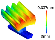
Helical gears are considered to have the shape of an extremely slim spur gear that is layered in the direction of the facewidth of the gear teeth while gradually changing the angle (Illustration 2). In other words, it is a shape in which slim spur gears mesh one after another while slowing down as they rotate. Therefore, if there is one pitch of misalignment in the direction of the facewidth of the gear teeth as shown in Illustration 3, in other words when εY is 1.0, it seems that all of the stress waves from each of the slim spur gears cancel each other out (Illustration 4). This is thought to be the reason why noise is minimal at εY = 1.0. |
|||||||
 |
| Illustration 2 : Geometric concept of helical gear meshing |
|---|
 |
| Illustration 3 : Helical gear with overlap contact ratio=1.0 |
|---|
 |
| Illustration 4 : Noise reduction mechanism for helical gears |
|---|
| 3. Effect of the installation accuracy of spur gears and helical gears | |||
The effect of installation accuracy on noise coming from the tilt of the axis is a very frequent topic of conversation, and we often hear in the market that "noise will improve if you eliminate the tilt of the axis." This presumption is likely accurate, but at Polyplastics we tried to quantify it to be able to respond with more than just |
|
||
| conjecture to inquiries we receive on the matter. We actually focused on the skewed shaft angle (offset error) as shown in Illustration 5, and we learned that noise does not necessarily get worse when the axis tilts. | |||
 |
 |
|
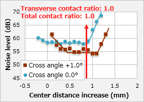
| Combination: Both M90-44 / grease lubrication Gear specs: m=1.0, helix angle= 0°, number of teeth=30, facewidth=15mm Rotation conditions: 500rpm, torque: 0.03N m |
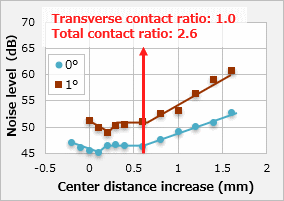
Combination: Both M90-44 / grease lubrication Gear specs: m=1.0, helix angle=20°, number of teeth=28, facewidth=15mm Rotation conditions: 500rpm, torque: 0.03N m |
|
| Illustration 6 : Spur gear noise and skewed shaft angle | Illustration 7 : Helical gear noise and skewed shaft angle | |
|---|---|---|
The noise measurement results when changing the center distance depending on whether or not there is a skewed shaft angle are shown in Illustration 6 for spur gears, and Illustration 7 for helical gears. We can see that spur gears and helical gears exhibit different behavior. |
| Impact of center distance with skewed shaft angle of 0° (spur gear): Illustration 6 / blue line |
Noise levels are lowest in the area where increase in center distance is between 0 and 0.8mm, and it tends to flatten out. Noise increase under 0mm results from forcibly rotating the gears while tooth interference is occurring. On the other hand, noise increases beyond 0.8mm because the (total) contact ratio is less than 1.0. When the ratio is this low the gear theoretically cannot rotate at constant speed, and the slowdown in rotation of the driven gear recurs in each tooth. For the sake of simplicity, we will refer to noise tendencies relative to center distance as the "bottom state" in the descriptions that follow. |
| Impact of center distance with skewed shaft angle of 1° (spur gear): Illustration 6 / brown line | |||
We can see that when spur gears have a skewed shaft angle, noise reduces as the "bottom state" noise tendencies mentioned above shift overall to the direction where center distance is larger. The decrease in noise is an unexpected result, but it seems that noise decreased as the friction coefficient decreased due to one-sided contact on the end surface, and the effect of tooth profile error was absorbed due to deformation of the teeth |
|||
| (Illustration 8) which has a similar effect to the use of soft materials.
Next, we will discuss the reason why "bottom state" noise tendencies shift overall to the direction where center distance is larger. First of all, interference occurs if the axis tilts with no backlash at center distance of zero, so we have no choice but to increase center distance to prevent interference. The noise increase points on the side with large center distance likely shift resulting from an increase in actual contact ratio due to one-sided contact deformation. |
|
||
| Impact of center distance with skewed shaft angle of 0° (helical gear): Illustration 7 / blue line |
Noise levels are lowest in the area where increase in center distance is between 0 and 0.6mm, and it tends to flatten out. Noise increase under 0mm is due to the same reason as in spur gears. On the other hand, noise increases beyond 0.6mm because the transverse contact ratio is less than 1.0. Helical gears have a phenomenon called overlap ratio. Total contact ratio is the sum of transverse contact ratio and overlap ratio, and theoretically total contact ratio must be 1.0 or higher for rotation at constant speed on the driven side. Although total contact ratio is greater than one (total contact ratio 2.6), noise increases due to the following reasons. |
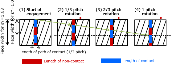 |
* Shown with transverse contact ratio = 0.5, overlap contact ratio (εY) = 1.63 |
| Illustration 9 : How teeth engage when transverse contact ratio is less than 1 |
|---|
Transverse contact ratio less than 1 means that the length of path of contact is less than one pitch. In other words, there is a space in which teeth do not touch within the space of one pitch (Illustration 9). If this is a spur gear it will be unable to rotate at constant speed and noise will increase as a result. However, helical gears will have a total contact ratio of 1 or higher and will thus be able to keep operating at constant speed. The helical gear that we used for our test was εY = 1.63 and it was not the best situation as the overlap ratio was not an integer. As shown in Illustration 10 (1), the stress waves at the part where εY = 1 are working to cancel each other out, but waves are being emitted from the remaining εY = 0.63 in which they are not cancelling out. Also, if the transverse contact ratio is less than 1, the gear facewidth that is actually meshing is theoretically only the width of the apparent facewidth multiplied by the transverse contact ratio. However, as Illustration 10 shows, as the engaging gear facewidth decreases it seems that noise increases because the effect of stress waves cancelling out is further reduced. |
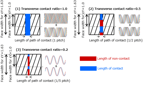 |
| Illustration 10 : Mechanism of reduced stress wave cancel-out effect when transverse contact ratio is less than 1 |
|---|
| Helical gears with skewed shaft angle produce more noise in the bottom state range: Illustration 7 / brown line |
Helical gears show precisely the opposite behavior of spur gears. As shown in Illustration 4, noise is lowest with overlap ratio of 1.0, and we explained this was because of stress waves cancelling each other out. Assuming the helix angle is the same, the larger the facewidth the larger overlap ratio will be. Incidentally, if there is offset error, there will be one-sided contact on the end surface and the facewidth that is actually meshing will significantly decrease. This will in turn decrease the actual overlap ratio. This is why behavior differs from that of spur gears. |
| 4. Conclusion |
As a follow-up about noise reduction methods for plastic gears we have quantitatively explained points to note in effective noise reduction for helical gears. Plastic gears must be handled with sufficient understanding of the behavior particular to plastics. As Japan's top manufacturer of POM, Polyplastics owns at least a 60% share of the market, and we are also actively making proposals for designs that deliver noise reduction, high strength, and high-accuracy-which sufficiently take the properties of the material into consideration. We are also actively making comprehensive proposals that include gearbox materials and design. At Polyplastics we are continuously working on technological development to be able to propose even higher levels of quality, with dedication to contribute to higher quality in our customers' products. |
[Related information] |
| Technical data sheet is available online: |
|
||||
| For inquiries about our technologies and materials, please contact us via: |
◆Polyplastics Group Representative | ||||
| ◆WEB Inquiry |
19th May 2021 |


