Home > Technical Support > Gears
Noise reduction technology for plastic gears
| 1. Introduction |
Engineering plastics are widely utilized in parts of mechanisms—such as gears, bearings, cams, rollers for sliding doors, and other types of rollers—of various equipment such as audio visual systems, office automation equipment, consumer electronics, automobile parts, precision machinery components, toys, and stationery. Most engineering plastics are made from crystalline resins, which exhibit superior resistance to wear and fatigue. Polyoxymethylene (POM) accounts for the majority of these plastics made from crystalline resins.1) In comparison to other engineering plastics in the same price range, such as polyamide (PA) and polybutylene terephthalate (PBT), POM offers both higher strength and greater rigidity in the 60 to 80℃ (from 140°F to 176°F) temperature range, which is typical for specifications of automobile parts and office automation equipment. This allows it to be used unfilled. Being an unfilled material enables the manufacture of components that exhibit lower wear and higher precision, making it arguably the best choice of material for use in parts of mechanisms. Although Polyplastics is a manufacturer of materials, since our founding our offerings to the market have included proposals on design technology, in addition to materials. As a result, our DURACON® POM maintains a greater than 60% share of the Japanese market for POM resins. Supporting design technology for plastic gears—which is the theme of this paper—is one such offering. There is a tendency to believe that design technology falls outside the scope of work of a materials manufacturer. However, as an expert in engineering plastics, Polyplastics has contributed to improvements in the quality of products across a wide variety of fields, through our design technology solutions. For example, during the time at the end of the 20th century, when development of video tape recorders (VTRs) was tremendously popular in Japan, all manufacturers of home electronics were grappling with the issue of how to reduce noise from plastic gears. In order to achieve these noise reductions, manufacturers need to properly understand the particular ways in which plastics behave differently from metals. We take pride in the fact that our design technology support made a major contribution to plastic gear noise reductions achieved during this period. We have now developed these technologies even further, taking them beyond the scope of home electronics products such as VTRs and applying them to every conceivable field. Here we will introduce some of our plastic gear noise reduction technologies. |
| 2. Types of Gear Noise | ||||
While it cannot reveal all of the causes of gear noise, it is important to perform frequency analysis to obtain the minimum level of information needed to investigate the causes behind occurring noises. Figure 1 shows the frequency spectrum of noise generated when two POM gears (standard unfilled POM copolymer) mesh during operation. In this experiment, the gear noise is comprised of the three types of sound shown in the figure. B and C are the natural frequencies of the equipment and the plastic gears, and these are generally low levels of noise in most cases. The important one is A, which is typically known as gear mesh |
|
|||
| frequency. We characteristically see a frequency that corresponds to the number of times the gear teeth mesh per second, and also an integral multiple of this frequency. As this gear mesh frequency accounts for the majority of noise in most cases, it is important to understand its underlying causes. | ||||
| 3. Causes of Gear Mesh Frequency and Examples of Preventative Measures |
There are three typical causes of mesh frequency in plastic gears. (1) Repeated changes in the number of pairs of teeth meshing with each other (2) Reversal of friction vector for pitch points (3) Pitch compatibility with the mating gear (1) is a general idea that also applies to metal gears, but (2) and (3) are causes that are particular to plastics. Below are brief descriptions of these causes and the ways to counteract them. |
| 3-1 Repeated Changes in the Number of Teeth Meshing with Each Other |
There is a parameter for gears called contact ratio, and for a standard spur gear this ratio is above one but less than two. Figure 2 shows that as the gears turn, they alternate between meshing with one pair of teeth and two pairs of teeth. Since there is a difference in the extent to which the teeth deform depending on whether torque is absorbed by one or two pairs of meshing teeth, the deformation fluctuates cyclically as each tooth meshes, as shown in Figure 3. Gear mesh frequency occurs as a consequence. This can be counteracted by using materials with higher stiffness. However, in the case of plastic, this almost always has the reverse effect. The reason is that plastic gears are normally filled with glass fibers, and resulting factors caused by shrinkage anisotropy, such as reduced precision and increased surface roughness, lead to an increase in noise. Conversely, there is also the approach of using extremely soft resins to promote deformation so that there are always two pairs of teeth meshing, but this approach poses limitations in terms of strength. Therefore, typical designs adopt a contact ratio of at least 2, alternating between two and three pairs of meshing teeth. Helical gears and high-tooth gears are more specific examples of such methods, and we encourage you to refer to technical literature on gears to learn more about these. |
 |
 |
| Figure 2: Model of the changing number of meshing teeth |
Figure 3: Changes in rotational angle caused by deformation |
|---|
| 3-2 Reversal of Friction Vector for Pitch Points |
The torque of gears is transferred in a vertical direction relative to the surface of the teeth. This direction of transmission of the force is typically called the normal line, and the ideal scenario is for the direction of transmission of the force associated with the rotation of the gears to remain constant. However, in reality, the sliding friction of the teeth causes the direction of transmission of the force to change constantly. The teeth contact each other with curved surfaces, and though at a glance it appears they are rolling, the teeth are actually "approaching" each other diametrically as they start to mesh, after which they finish meshing by "receding" diametrically. This brings about sliding. The moment that this "approaching" changes to "receding" is when the direction of sliding friction reverses. The relation to the normal line is as shown in figure 4; the direction of synthetic driving force of the normal line and friction vector instantaneously changes each time one tooth meshes with another. In these cases, using materials with a low coefficient of friction is an effective measure against noise, as reducing frictional force allows changes in synthetic driving force along the normal line to be minimized. DURACON M90-44 is the most widely-used grade in the manufacture of plastic gears in Japan. However, DURACON NW-02-which was developed for use in gears-offers exceptional gear noise improvements (figure 5). It also has a track record of approximately 20 years of use in a wide variety of applications, particularly in devices where noise is a major consideration, such as copiers, laser printers, and inkjet printers. DURACON LW-02 is a material that achieves further improvements in this area, offering noise reductions of over 10 dB compared to DURACON M90-44, as shown in figure 5. |
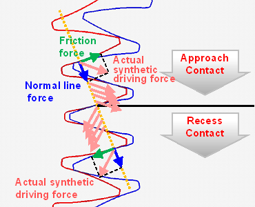 |
| Figure 4: Force borne by the gears |
|---|
 |
| Figure 5: Gear noise data |
|---|
| 3-3 Pitch Compatibility with the Mating Gear |
Ideally, it would be possible to accurately calculate the level of shrinkage that injection-molded gears experience during the molding process. However, there are virtually no gears for which this is perfectly estimated. Unlike metal gears, which exhibit less shrinkage, there are many cases with plastic gears where the normal pitch-a factor that is critical to gear meshing-is not as it was designed. As figure 6 shows, the normal pitch of the driving gear and the driven gear must be equal for them to mesh correctly. Normal pitch is expressed by the following formula.
Normal pitch = mΠcosα (Formula 1) m: module Π: ratio of a circle's circumference to its diameter α: pressure angle As deviations to the estimated shrinkage will cause variance of the module, formula 1 dictates that normal pitch will also become skewed. There would be no issue if the normal pitch of the mating gear becomes equally skewed; however, this is rarely the case, and the normal pitches frequently do not match. POM gears were manufactured under a wide range of different molding conditions, resulting in various normal pitches. Figure 7 shows the results of noise measurements taken when these gears were combined. It shows a correlation between the amount of noise and the degree of difference in the normal pitches of the driving gear and driven gear. As the normal pitch of this gear is 2.95 mm, a 0.01 mm difference in normal pitch corresponds to approximately 0.3%. Noise changes by as much as 5 dB as a result of this difference. However, considering the fact that a 10 MPa change in injection pressure results in a 0.1% change for unfilled POM, it is apparent that noise can be largely controlled by adjusting the molding conditions. The ability to greatly reduce noise simply by modifying the molding conditions in the final stage of mass production is extremely significant. |
 |
| Figure 6: Compatibility of normal pitch |
|---|
 |
Figure 7: Relationship between noise level and difference of |
|---|
| 4. Conclusion |
Noise reduction for plastic gears requires methods that take into account the particular ways in which plastics behave. As a leading manufacturer of POM, Polyplastics not only offers materials solutions, but also design solutions for noise reduction. We also actively offer comprehensive solutions that include gearbox materials and design. We are continuously developing new technologies that we are confident will contribute to improving the quality of our entire range of products. |
| Technical data sheet is available online: | ◆M90-44 ◆NW-02 ◆LW-02 ►Grade comparison table |
| For inquiries about our technologies and materials, please contact us via: |
◆Polyplastics Group Representative |
| ◆WEB Inquiry |
| [ Reference ] | 1) CMC Publishing Co., Ltd. Tribological Control of Polymer and its Application. May 2015 |
5th September 2017 |