Home > Technical Support > Molding Technology
New Evaluation Method to Identify the Mechanism of Gas Formation During Injection Molding
New Evaluation Method to Identify the Mechanism |
|---|
| 1. Introduction |
In the previous report, we introduced the Gas Investigation Method in Injection Molding (GIMIM), our own proprietary method to collect and evaluate the gases formed during molding. We also explained our findings related to the process by which pyrolysis gas forms during injection molding and the mold deposits (MDs) caused by this process (*1). Many of our customers read our previous report and expressed strong interest in gas-related problems. Here we will take a closer look at gas burns, which are another form of gas-related problems, and share our assessment of the mechanism as well as measures to take in response. |
| *1: |
New Evaluation Method to Identify the Mechanism of Gas Formation During Injection Molding Part 1: Applied to Mold Deposits Caused by Pyrolysis Gas |
| 2. Problems arising from pyrolysis gas |
Gas burns are caused by adiabatic compression occurring when resin decomposition gases and air get trapped inside the mold (Figure 1). Normal molds have gas vents and parting lines, hence gas burns do not often occur. However, continuous molding can cause gas vents to clog, and adiabatic compression will similarly result in gas burns (Figure 2). We cannot identify the origin of the substances that cause the vents to clog, which means that the cause remains unclear, and the phenomenon is extraordinarily difficult to reproduce. |
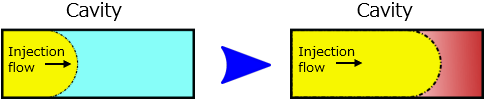 |
Figure 1 : Illustration of gas burns from trapped air & gas |
|---|
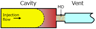 |
Figure 2 : Illustration of gas burns with clogged vents |
|---|
| 3. Measures adopted considering the mechanism of gas formation |
| 3.1 Gas resulting from energy loss at the time of injection |
In the previous report, we explained that gas formed during plasticization is discharged from the hopper side, and gas flowing into the mold is formed during injection. Large amounts of gas form during injection mainly because of large energy loss in the nozzle. The nozzles of typical injection molding machines are comprised of a drastically contracted structure, and energy loss arises due to the shape. |
 |
Figure 3 : Flow of drastic contraction in injection molding machine nozzles |
|---|
This drastically contracted structure is not only in nozzles. Gates of molded articles also have this same structure. This shape-induced energy loss is generally proportional to the flow rate squared, hence the faster the injection speed, the more energy loss that turns into heat, leading to large amounts of pyrolysis gas formation. From this we can conclude that we should reduce flow rate and use gates and nozzles with shapes that are not conducive to energy loss in order to limit gas formed by the injection molding machine. The following methods could be used to reduce flow rate. (1) Lower the injection speed setting (2) Use multiple gates (3) Use multiple cavities (4) Increase the size of the gate and nozzle (The ΦD1 part of Figure 3) |
| 3.2 Uneven thermal conduction within the injection molding machine barrel |
To plasticize the resin pellets, we typically use shearing heat at the time of plasticization and the heat from heaters outside the barrel. Molten resin is continuously subjected to heat from the heaters until it is injected. Figure 4 is a schematic diagram of heat levels applied to resin in the cylinder. The heat source is on the outer side of the resin and the structure transmits heat to the inner side via thermal conductivity, from which we can understand that there is a difference between the heat levels on both the outer and inner side. |
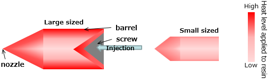 |
Figure 4 : Schematic diagram of heat levels applied to resin in the cylinder |
|---|
The longer the distance between the center and outer portions of the resin, the larger the temperature difference becomes. When time passes, pyrolysis begins to occur in the resin stagnating along the wall side. The following measures could be taken to prevent problems from this type of uneven thermal conductivity. (1) Do not choose injection molding machines that are excessively large relative to the molded articles (2) Reduce cylinder temperature as much as possible (3) Avoid mold-contact molding so that heat loss from the mold does not occur. Alternatively, add a heat insulation layer to the parts in contact with the mold (4) Be careful of changes to surrounding temperature so that heater output does not get too high |
| 3.3 Substances that cause gas burn defects and the mechanism of vent clogging |
Among the various gas substances measured by GIMIM, high boiling substances are more likely to get stuck to the mold than they are to be discharged. Conversely, low boiling substances are generally more likely to be discharged. From the test results below, we can see that there is no linear relationship between the mold deposits that cause vent clogging and the volume of high boiling substances. Using a test mold for evaluating vents, we illustrate the relationship between gas volume and limit shot count (number of shots until gas burns occur) for multiple PPS grades (Figure 5). We can see there is hardly any correlation between limit shot count and total gas volume or high boiling gas volume. |
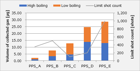 |
Figure 5 : Graph of relationship between limit shot count and gas volume |
|---|
Analyzing with GIMIM, we can estimate that vent clogging is caused by the workings of a complex relationship between the volumes of low boiling substances, high boiling substances, total volume of substances within decomposition gas. Additionally, high boiling substances get stuck to the vents where they turn into mold deposits, and there have been reports of clogs being cleared by blowing away these deposits with air and low boiling gas. The following methods could be used to prevent gas burns caused by clogged vents. (1) Lower cylinder temperature as much as possible so that pyrolysis does not occur (2) Use a rag or similar object to frequently wipe away mold deposits that are lightly stuck to the gas vents (3) Refer to the measures listed in sections 3.1 and 3.2 and implement them as needed |
| 3.4 GIMIM application: Verifying the purging process | ||||||||||
There had been no way to verify the effects of the purging process other than visual confirmation after actually molding several thousand to tens of thousands of shots. Since GIMIM can detect substances in units of ppm, we can now use it to verify whether the purging process was conducted properly with only a small number of shots. Various factors such as the differences between the polarity, viscosity, and compatibility of materials determine whether or not the materials are removed through the purging process. Typically, it is considered unlikely that resin inside the cylinder can be completely removed. However, with the selection of purging materials we can reduce residual resin volume to a level similar to that achieved with disassembly and cleaning. Test results from different purging processes are shown below (Figure 6). Conditions A and B use the exact same molding machines, molds, molding conditions and evaluation materials, with the only difference being the purging materials. We performed a gas analysis during the final PPS molding.
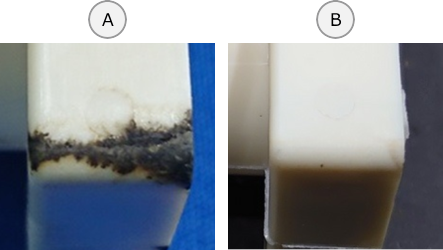
We see that gas burns occurred at the end of the flow after several shots under Condition A, but under Condition B the gas burns are gone and the intensity of the gas in Figure 7 is also lower. |
||||||||||
 |
|
Figure 6: Comparison of gas burns from different purging conditions |
|---|
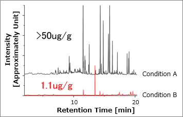 |
Figure 7: GIMIM comparison of gas substances under each set of conditions |
|---|
Under Condition A, decomposition gases from the purging materials and remaining PPS are detected. With the purging method under Condition B, only pure PPS substances are detected, and pyrolysis gases have been drastically reduced. Next, we compared residual persistence of pyrolysis gases according to combinations of materials and purges (Table 1). Relative comparisons are made for volumes. |
Testing method |
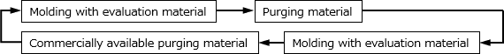 |
We repeated this cycle and analyzed the gas during molding of the evaluation material.
Looking at the results, we see that there are many cases where gases arise from what remains after the purge, and that there are variations in the effects of purging. In the test results for POM, PBT and PPS we can also see that commercially available purging materials are effective. |
Table 1 : Evaluation material and residual persistence of gas |
| Evaluation material | ||||
Purging material |
POM | PBT | PPS | LCP |
PP with GF |
Purging material: Remains |
Purging material: Remains |
- |
- |
PC with GF |
- |
- |
Purging material: Extremely small amount remains |
Purging material: Extremely small amount remains |
High density PE |
Not detected |
Purging material: Remains |
Purging material: Remains |
Purging material: Remains |
POM |
Not detected |
- |
- |
- |
PBT |
- |
PBT: Small amount remains |
- |
- |
PPS |
- |
- |
PPS: Remains |
- |
LCP |
- |
- |
- |
LCP: Remains |
Commercially available purging material (1)* |
- |
Not detected |
Not detected |
- |
Commercially available purging material (2)* |
Not detected |
- |
- |
- |
*Made by Daicel Miraizu Ltd. |
| 4. Conclusion |
Using our new GIMIM method, we are now able to gain new knowledge about pyrolysis gases that are thought to cause gas-related and mold deposit problems during molding. However, there are still many things that we have not completely figured out, so verifications must continue. We will be conducting further research and studies using GIMIM, as we continue providing new solutions to gas-related and mold deposit problems while developing materials and grades that reduce the occurrences of these problems. |
| [Related information] | |
• |
|
Technical data sheet is available online: |
|
||
For inquiries about our technologies |
◆Polyplastics Group Representative | ||
| ◆WEB Inquiry |
13th September 2021 |