Home > Technical Support > Molding Technology > Molding Technology for DURANEX(R) PBT
Mold Design
5.1 Runner Design It is ideal to design runners so that the cooling of molten resin and pressure loss are as little as possible, but such design is not economical because the ratio of runner weight to product weight increases, and the cooling of runners becomes the determining factor of the molding cycle. It is recommended, therefore, that runners be designed with the smallest dimensions within the allowable range. "Simplified Runner Designing Chart" illustrated in "Molding Technology for DURACON® POM" can be used for runner design of DURANEX® PBT without any significant errors. As for runner shapes, the best type is a full round runner; however, this type of runner is costly because it is necessary to cut grooves on both the stationary and the movable mold halves. Therefore, trapezoidal runners are frequently adopted.The standard dimensions for this runner are as follows: Upper base length = (0.6 to 0.7) × Lower base length Depth ≈ Upper base length DURANEX can be molded through hot runners, but the following precautions must be taken: (1) When glass fiber reinforced grades are molded, materials for hot tips and manifolds must be carefully selected so that serious abrasion by the glass fibers does not occur. (2) It is necessary to avoid discoloration and deterioration of the resin caused by additional residence time in hot tips and manifolds. There should be no problems for other points, if only the general precautions on hot runner design are taken.
A larger gate is recommended for DURANEX than DURACON because reduction in cavity pressure tends to cause deformation. However, gate seal times for DURANEX are shorter than those for DURACON, as shown in Table 5-1, which is favorable from the molding cycle point of view. The key points for gate are as follows: (1) The gate type must be decided, taking product quality, productivity and automated operation into consideration. (2) The position and the number of gates affect deformation, strength (especially the weld strength of composite grades) and appearance of a part. These are important measures for preventing deformation. (3) The gate thickness should generally be 60 to 70% of the part thickness. Table 5-1 Gate Seal Times for DURANEX® PBT and DURACON® POM
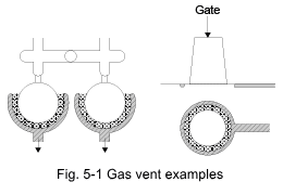
Improperly designed gas vents give DURANEX parts burn marks, impairing their appearance. As mentioned previously, high speed injection is a popular way to improve surface gloss; therefore, a thorough study of gas vents is required. For a mold where gas is driven out from the parting line, the recommended method is for gas to escape from the full outer periphery of the product as seen in Fig.5-1. The depth of the vent must be 2/100mm or less.
As a rule, a mold should be designed without undercut. In the case of DURANEX 3300, large undercut is not possible. The maximum is approximately 0.5%.
Draft should be as large as possible, within the permissible range, because of the small mold shrinkage of reinforced grades of DURANEX. Minimum taper is 1/2 to 1 degree. Sufficient consideration must also be paid to the knockout system, including the position and number of knockout pins.
Because mold temperature greatly affects the molding cycle and product quality, temperature control system for the mold must be studied beforehand as carefully as the runners, gates, and knockout system. The key points are: (1) Does the control system consist of electric heaters or hot water circulation? (2) The key points for hot-water circulation system are: a) Secure sufficient heat transfer surface area. b) Locate the cooling water channels as close as possible to the cavity (to get a uniform temperature profile of cavity surface). c) Circulate sufficient amount of water. In other words, it is important to use a temperature control unit having a pump big enough to supply sufficient amount of water to overcome pressure loss in the circuit. (3) Consideration of core cooling, which can greatly improve molding cycle and product deformations.
Mold material for DURANEX requires the following considerations. (1) Wear due to glass fibers (2) Corrosion caused by gases from decomposition (3) Corrosion resulting from flame retardants Hardening is the best way to minimize wear. A countermeasure to protect against corrosion is to select suitable mold material. To obtain reference data for corrosion resistance, test specimens of various steels were exposed to gases produced by various grades of DURANEX held at 260°C, and the discoloration and corrosion of the specimens' surfaces were observed. The samples fell in the following order. 420 > D2 > P21 > P20 > 1049 Also, the following sequence is reported in technical literature. 310S, 440C > 304 > D2 These results indicate that stainless-type steels can withstand corrosion better than others. For reference, features of various mold materials are summarized in Table 5-2. Table 5-2 Characteristics of Mold Materials
|
|||||||||||||||||||||||||||||||||||||||||||||||||||||||||||||||||||||||||||||||||||||||||||||||||||||||||||||||||||||||||||||||||||||||||